Arrays - Green Screen

Arrays help us to store and work with groups of data of the same type. The data is stored in consecutive memory spaces which can be accessed by using the name of the array and indexes or subscripts that indicate the position where the data is stored. Repetition structures provide us a simple way of accessing the data within an array. In this laboratory experience, you will be using nested loops to process bi-dimensional arrays and implement the functionality of a green-screen.
Objectives:
Practice accessing and modifying elements in an array.
Use nested loops to implement greens-screen techniques.
Use arithmetic expressions and selection structures to transform pixel colors.
Read pixels from an image and decompose them in their red, green and blue components.
Pre-Lab:
Before coming to the laboratory you should have:
Reviewed the basic concepts about repetition structures, nested loops, and bi-dimensional arrays.
Understood the methods of the
QImageclass for pixel manipulation.Studied the concepts and instructions for the laboratory session.
Visited the following Facebook page to see how the green technology is used in some Hollywood movies: https://www.facebook.com/video.php?v=920387528037801
Taken the Pre-Lab quiz, available in Moodle.
Green-Screen technology
In this laboratory experience, the student will be exposed to the basics of the green screen technology used in newscasting, motion pictures, video games, and others. Green screen compositing, or more generally known as chroma key compositing, is a technique for combining two still images or video frames[1]. Chroma key compositing, or chroma keying, is a special effects / post-production technique for compositing (layering) two images or video streams together based on color hues (range)[2]. Chroma keying can be done with backgrounds of any color that are uniform and distinct, but green and blue backgrounds are more commonly used because they differ most distinctly in hue from most human skin colors.
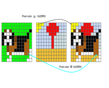
In this laboratory, we provide a simple GUI that allows the user to load an image with any solid background (although green or blue are preferred), and a background image. Your task is to implement a function that creates a third, merged image, in which the image with the solid background appears over the background image (with the solid background removed). Figure 1 shows an example of the expected results.
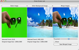
Figure 1: Example of the expected results. The object of interest is the hand carrying the sunglasses.
For illustration purposes, let's call the image with the solid background image A and let's say that the solid color in the background has an RGB 0x00ff00 (pure green). We will refer to the image with the interesting background as image B. Let's also assume that both images are the same size (width and height).
To produce the merged image (image C), we could start by completely copying image B to image C. Then, to insert only the object of interest into the merged image we could traverse image A pixel by pixel. We would compare the color of each pixel p in image A to the color 0x00FF00, if they are similar we do nothing (because it means that this pixel is part of the solid color background). If the color of p is not similar to 0x00FF00, we modify the corresponding pixel in image C, copying the color of the object's pixel to the merged image.
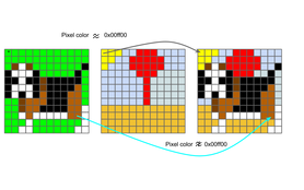
Figure 2 - Illustration of how the algorithm decides which pixels to include from image A into image C.
Pixels
The smallest element in an image is called a pixel. This unit consists of a single color. Since each color is a combination of tones for the primary red, green and blue colors, it is coded as an unsigned integer whose bytes represent the tones of red, green and blue of the pixel (Figure 3). This combination is called the color's RGB which is an acronym for "Red-Green-Blue". For example, a pure red pixel has an RGB representation of 0x00ff0000, while a white pixel has an RGB representation of 0x00FFFFFF (since the color white is a combination of tones of red, green and blue in all of their intensity).
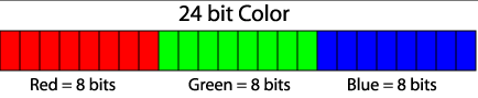
Figure 3. Bit distribution for the tones of red, green and blue in an RGB representation. Each tone can have values between 0x00 (the eight bits in 0) and (0xFF (the 8 bits in 1).
Qt uses the QRgb type to represent RGB values. Using certain functions that are described below we can obtains the red, green and blue components of the QRgb value of the pixel and manipulate the images.
Library
In today's laboratory experience, you will use the QImage class. This class permits access to the data in the pixels of an image to manipulate it. The documentation for the QImage class can be found in http://doc.qt.io/qt-4.8/qimage.html.
The code provided in this project contains the following objects of the QImage class:
originalImage// contains the information of the original image that you will editeditedImage// will contain the edited image
The objects of the QImage class have the following methods that will be useful for today's laboratory experience:
width()// returns the integer value for the image's widthheight()// returns the integer value for the image's heightpixel(i, j)// returns theQRgbfor the pixel in position(i,j)setPixel(i,j, pixel)// modifies the value for the pixel in position(i,j)to the value of pixelQRgb
The following functions are useful to work with data of type QRgb:
qRed(pixel)// returns the tone for the pixel's red colorqGreen(pixel)// returns the tone for the pixel's green colorqBlue(pixel)// returns the tone for the pixel's blue colorqRgb(int red, int green, int blue)// returns theQRgbpixel composed of the red, green and blue values received.
Examples
QRgb myRgb = qRgb(0xff, 0x00, 0xff);: Assigns the value0xff00fftomyRgbwhich represents the color
Notice that the value
0xff00ffrepresents the values0xff,0x0, and0xff, that correspond to the red, green and blue components inmyRgb.If the following
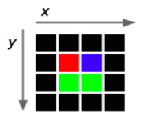
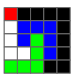
4 x 4image of pixels represents the objectoriginalImage,
then
originalImage.pixel(2,1)returns thergbvalue that represents the color blue (0x0000ff).The following instruction assigns the color red to the pixel in position
(2,3)in the edited image:editedImage.setPixel(2,3,qRgb(0xff,0x00,0x00));.The following instruction assigns to
greenContentthe value of the green tone that is contained in the pixel(1,1)oforiginalImage:int greenContent = qGreen(originalImage.pixel(1,1));.The following program creates an object of the
QImageclass and prints the red, green and blue components of the pixel in the center of the image. The image used is the one specified within the parenthesis during the creation of the object, that is, the filechuck.png
#include <QImage>
#include <iostream>

using namespace std;
int main() {
    QImage myImage(“/Users/rarce/Downloads/chuck.png”);
    QRgb    centralPixel;

    centralPixel = myImage.pixel(myImage.width() / 2, myImage.height() / 2);

    cout    << hex;

    cout    << “The red, green and blue components of the middle pixel are: “
        << qRed(centralPixel) << “, “
        << qGreen(centralPixel) << “, “
        << qBlue(centralPixel) << endl;
    return 0;
}
Measuring Similarity of Pixel Colors
Look at Figure 4, although the background in image A looks uniform, it really includes pixels of diverse (although similar) colors.

Figure 4 - What may seem as a solid color, really is not. Thus, we use the color distance.
Instead of only considering as part of the solid background the pixels whose color is exactly 0x00FF00, we measure a color's distance from the pure color. A small distance means that the color is almost a pure green. A large distance means that the color is very different from green. The equation for distance is:
where , , and are the red, green and blue components of the pixel being considered. , , and are the components of the solid background, e.g. in our example y .
A and Z of the QImage class, choose the best description of the following code:
greenComp = qGreen( A.getPixel(0,0) );
result = greenComp > 230 ? 0xff0000: 0x0000ff;
Z.setPixel( 0, 0, result);
Z to pure red if the green component of the pixel in image A is greater than 230.Z to pure blue if the green component of the pixel in image A is greater than 230.Z to pure green if the green component of the pixel in image A is greater than 230.greenComp = qGreen( A.getPixel(0,0) ); extracts the value of the green component of a pixel in the image A. If the value of greenComp is greater than 230, the value assigned to result corresponds to a pure red color.
if ( qRed( A.getPixel(0,0) ) == 0xff ) A.setPixel(0, 0, 0x0000ff); if ( A.getPixel(0,0) == 0xff0000 ) A.setPixel(0, 0, 0x0000ff);if ( A.getPixel(0,0) == qRed(0xff0000) ) A.setPixel(0x0000ff); 0xff without taking into account the values of the other components. The second option is the correct one since it compares the value of the pixel with the value of the pure red (0xff0000). The third option does not make an adequate comparison either because it tries to compare the pixel's value with the value of the red component.
A of the QImage class that has a width and height of 5 pixels, i.e. the pixel (0,0) is red, (4,0) is black, and (2,2) is green.
Which of the following would be the output of the following instruction: cout << qRed( A.pixel(1,0) )?
0xff 0x77 0x00 (1,0) is black (value 0x000000), therefore it's red component is 0x00.
A of the QImage class that has width and height of 5 pixels, i.e. the pixel (0,0) is red, (4,0) is black, (2,2) is green.
Which of the following would be the output of the following instruction: cout << A.getPixel(2,3)?
0x00ff00 0xff0000 0xffffff 0x000000 (2,3) is green, therefore it's value will be similar to 0x00ff00.
A?
for (int i = 0; i < A.width(); i++) A.setPixel(i, A.height()/2, 0); for (int i = 0; i < A.height(); i++) A.setPixel(A.width()/2, i, 0); for (int i = 0; i < A.width(); i++) A.setPixel(i/2, i/2, 0); i in both arguments and could result in exceeding the valid values of the image's height. The fourth option is false, since we do not need a nested loop to draw a simple line.
Laboratory Session:
In this laboratory experience, starting with an image with an object of interest over a solid color background and an image to use as a background, you will define and implement a function that creates a third merged image where the image with the object of interest will have its background color removed and will appear over the image chosen to be the background.
You will be working with the Filter.cpp file. The following is a review of the variables in this file:
objectImage: reference to the object image with the solid backgroundbackgroundImage: reference to the background image objectmergedImage: reference to the merged imagethreshold: is a threshold value used to compare the distances between the object pixel and the solid background pixel. In the provided code, the threshold value is read from the slideBar.ghost: is a boolean value used to apply ghost filter to pixels.(x, y): contains the coordinate of the pixel whose color will be used as solid background. The default value is (0,0).(offset_x, offset_y): the coordinate of the merged image where the upper-left corner of the objectImage should be inserted. The default value is (0,0).
Exercise 1 - Create a Composite Image
Instructions
Load the project
GreenScreenLabintoQtCreator. There are two ways to do this:- Using the virtual machine: Double click the file
GreenScreenLab.prolocated in the folder/home/eip/labs/arrays-greenscreenof your virtual machine. - Downloading the project’s folder from
Bitbucket: Use a terminal and write the commandgit clone http:/bitbucket.org/eip-uprrp/arrays-greenscreento download the folderarrays-greenscreenfromBitbucket. Double click the fileGreenScreenLab.prolocated in the folder that you downloaded to your computer.
- Using the virtual machine: Double click the file
Configure and run the program. The provided code creates the interface shown in Figure 5. The buttons Select Image and Select Background Image have already been programmed to perform their actions.
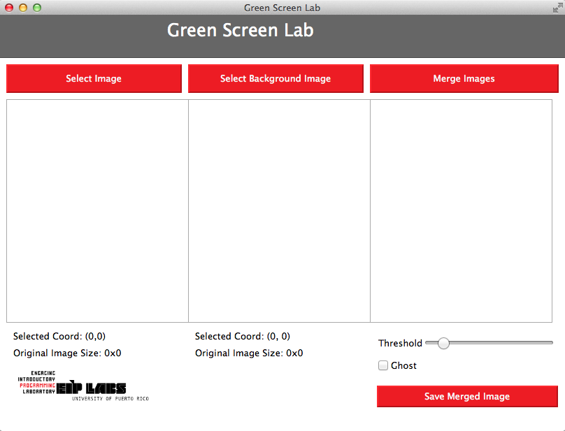
Figure 5.Interface for the green screen application.
Click the Select Image button to load the image that contains the solid background, the click Select Background Image to load the image that contains the interesting background. The folders called
green_backgroundandlandscapescontain some images that are suitable as the first and second images.Your first task is to complete the function
MergeImagesin fileFilter.cpp.MergeImagesis the function that is called when the user presses the button captionedMerge Imagesor when he slides the slide bar. The functionMergeImagesreceives the image with the solid background, the background image, a reference to the merged image, a threshold value, and the coordinates(x,y)of the pixel from which we will extract the sample green background color, and the coordinates(offset_x, offset_y)from the merged image.
For this first exercise you can ignore the following parameters: ghost, offset_x, offset_y. Your implementation should place the objectImage into the mergedImage starting at position (0,0).
The Algorithm
Acquire the value of the solid color. The solid color will be the color of the pixel in the coordinate
(x,y)of the object image with the solid background. The default value for(x,y)is(0,0).For every position
(i,j), read the color of the corresponding pixel in the objectImage. Compute the distance of the pixel colors to the solid color. If the distance between the solid color and the color of the pixel of the image is greater than the threshold, set the corresponding(i,j)pixel in the merged image to the objectImage pixel color.
Test your implementation by loading object and background images and verifying the merged image.
Exercise 2 - Creating a Composite Image using the ghost Filter
In this exercise you will modify Exercise 1 to apply a ghost filter to each of the pixels that will be composed over the background image (if the ghost variable is true). The filter creates a ghost like effect on the objects composed over the background image, as in Figure 6.
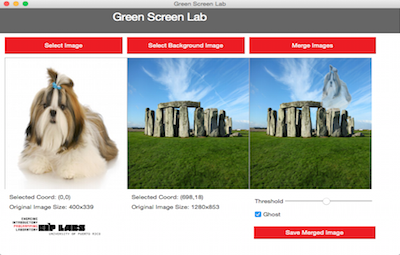
Figure 6 - In this example, the dog in the image with the solid background is composed in the background image with the ghost filter.
The ghost effect is achieved by averaging the background color with the object's color (instead of simply replacing the background with the object's color). The average is performed for each of the components (red, green and blue).
where , , and are the red, green and blue components of the new ghost pixel. , , and are the components of the object image. , , are the components of the background image.
Exercise 3 - Create a Composite Image placing the Object in a Specified Position
The widget that displays the background has been programmed to register the position where the user clicks. In this exercise you will program the MergeImages function so that the position where the user clicks on the background image is used as the top left corner where the object image will be displayed in the merged image. The figures 7 and 8 illustrate the effect. Note the Selected Coord values under the images.
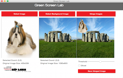
Figure 7. In this example, the background image has not been clicked. Thus the "Selected Coord" is at its default value of (0,0). The dog image is inserted with its top-left corner at (0,0) in the merged image.
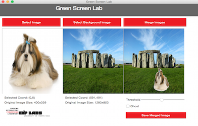
Figure 8. In this example, the background image has been clicked at coordinate (827,593). The dog image is inserted with its top-left corner at (827,593) in the merged image.
In this exercise your task will be the same as in Exercise 1, but this time you will need to offset the object image inside the merged image by the amount specified in the offset_x and offset_y parameters. Please take into consideration the merged image boundaries when you are inserting the object image. The user may specify an offset where the boundaries are exceeded and the object will be cut, as in Figure 9.
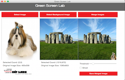
Figure 9. In this example, the user selected a position that assigned values that are too large for offset_x and offset_y; the implementation made the adjustment so part of the dog appeared in the merged image.
The example in Figure 10 shows how the object image will behave when merging it with the background image. The offset_x and offset_y variables represent the point in the background image where the upper left corner of the object image will be placed. Notice that if a point too close to the image border is chosen, part of the object image will be outside of the limits of the background image. As we have seen when manipulating arrays, if one tries to access or alter elements that are outside of the size range of the array, we get a fatal compilation error. The same thing happens with the images.
You should make sure that your implementation takes into account the offset_x and offset_y values so the composition does not try to access or alter pixels outside of the limits of the background image. If you try to access or alter pixels outside of these limits, it will result in a fatal error.
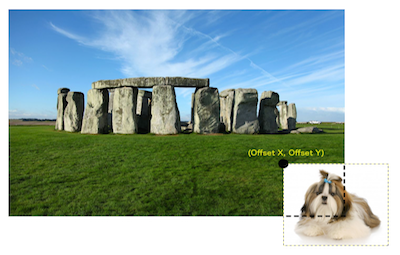
Figure 10. Illustration of the object image with pixels that are outside of the background image limits. If the possibility of this happening is not taken into account in the implementation, there will be a fatal error.
Validate your implementation by choosing several offsets and observing the merged image. Be sure to try cases in which you choose x and y offsets that result in the object being cropped in the merged image (as in Figure 9).
Deliverables
Use "Deliverable" in Moodle to upload the filter.cpp file that contains the MergeImages function. Remember to use good programming techniques, include the names of the programmers involved, and document your program.
References
[1] http://en.wikipedia.org/wiki/Green_screen_(disambiguation)